DIYMobileAudio.com Car Stereo Forum banner

E34 three way kicks, cement board baffles

35K views 189 replies 22 participants last post by  sydmonster  
#1 ·
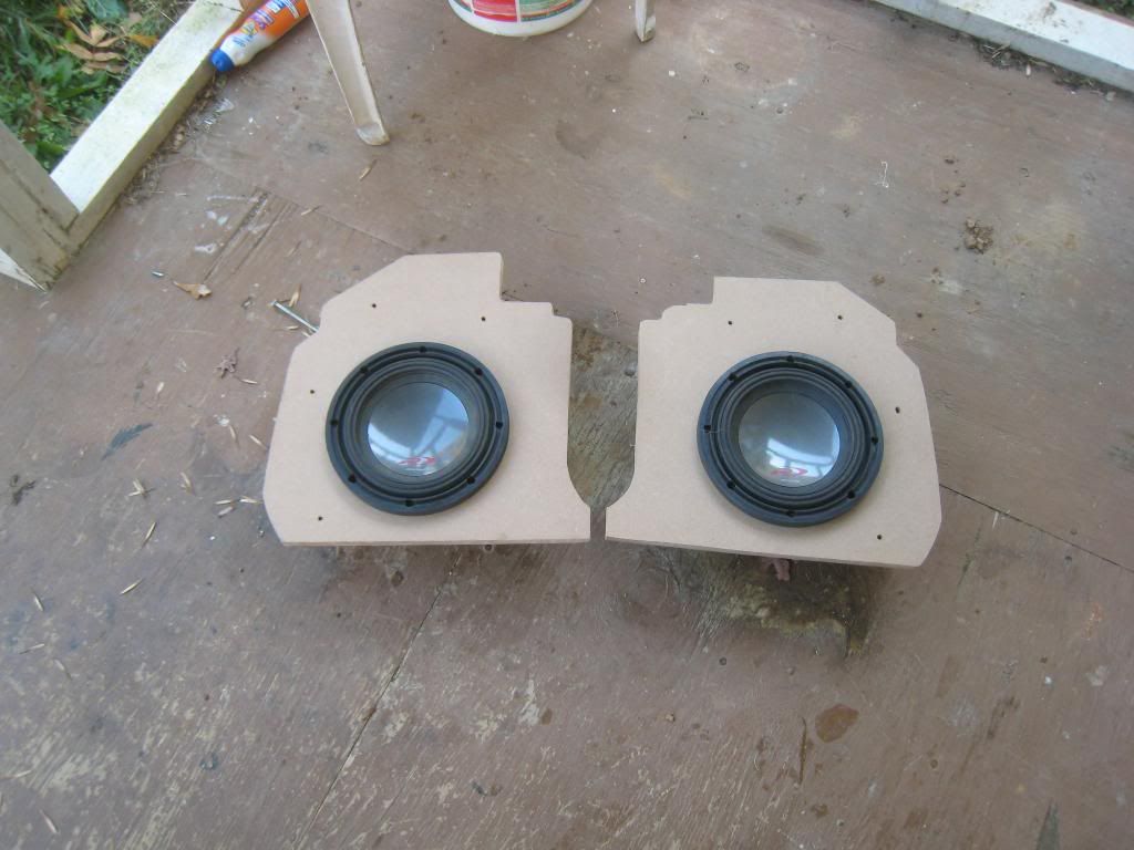
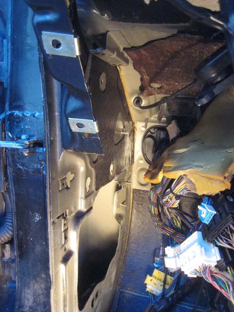
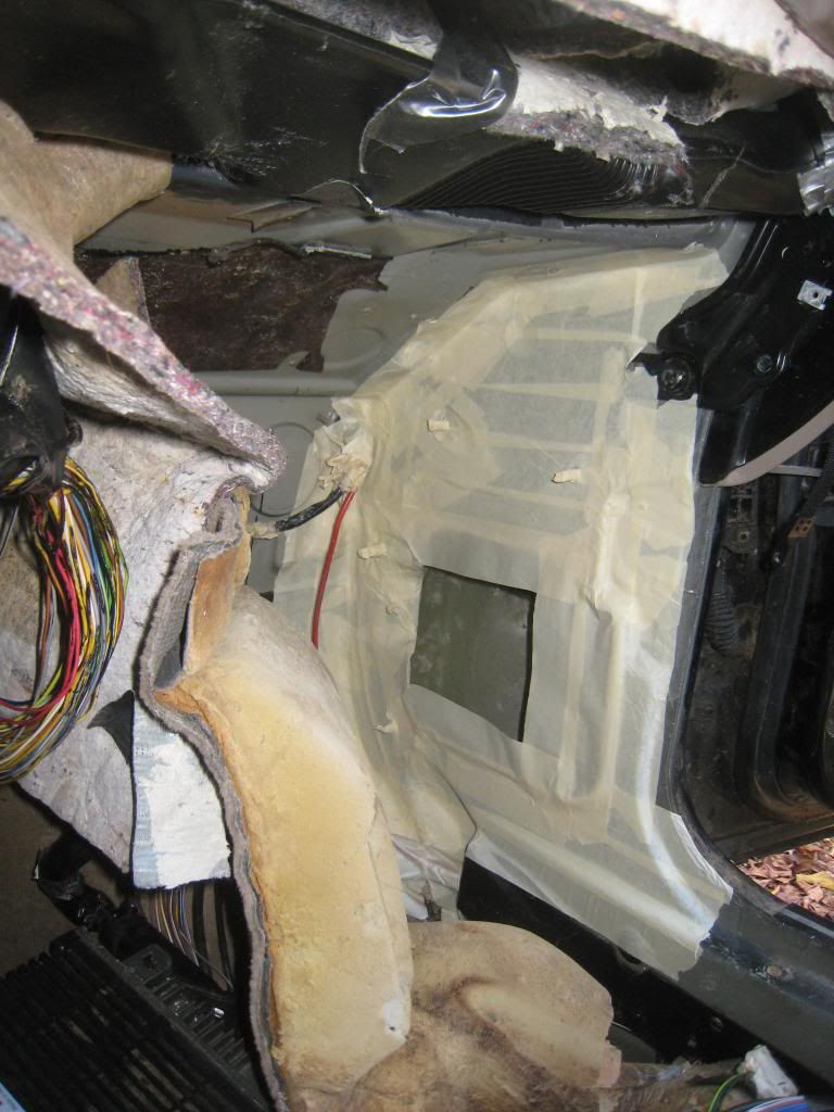
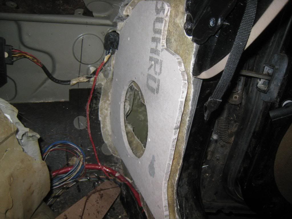
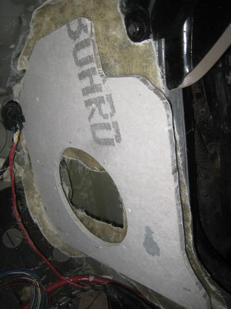
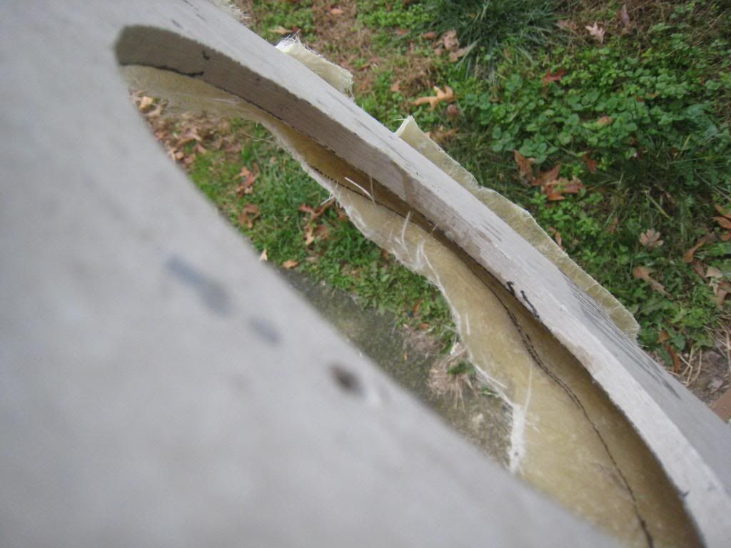
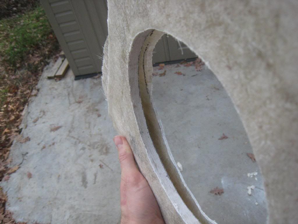
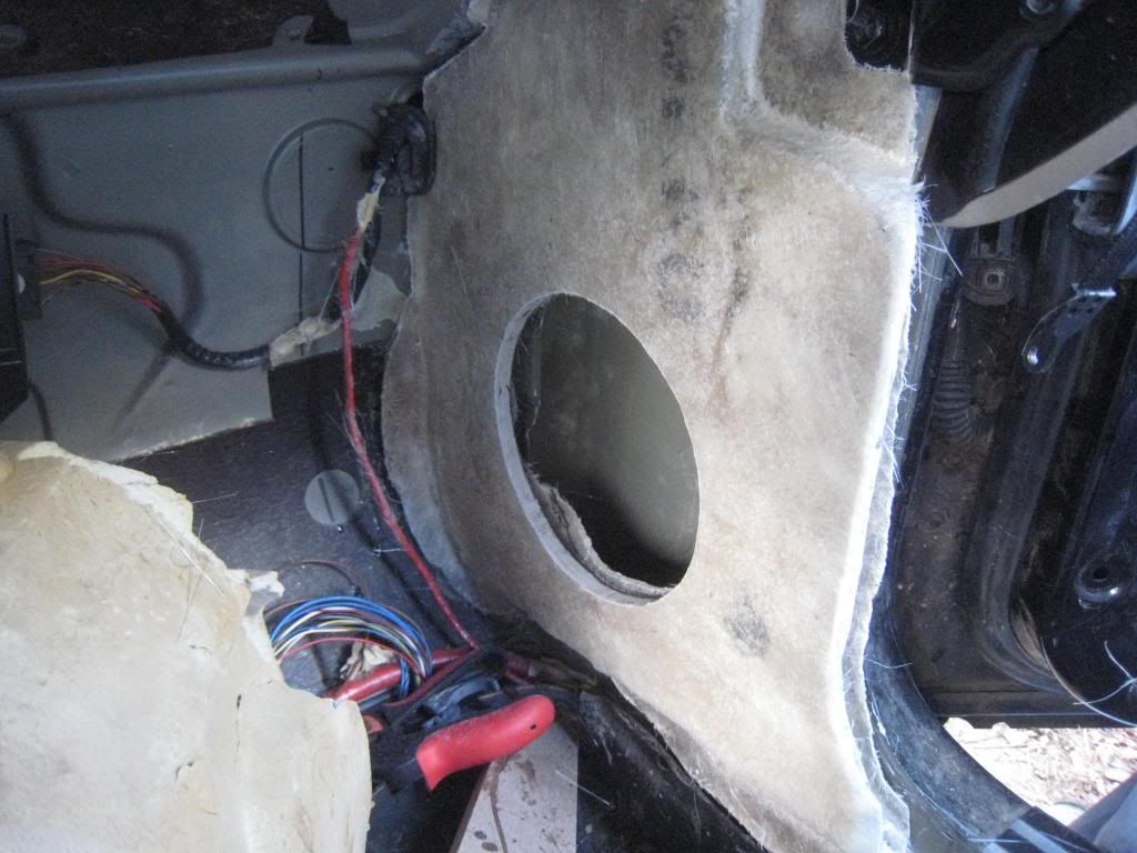
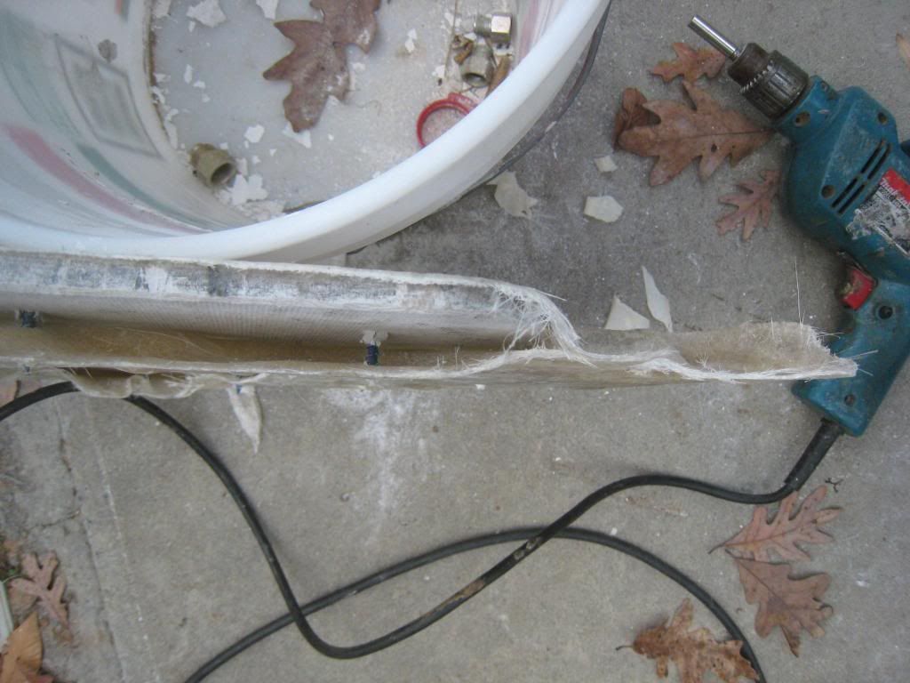
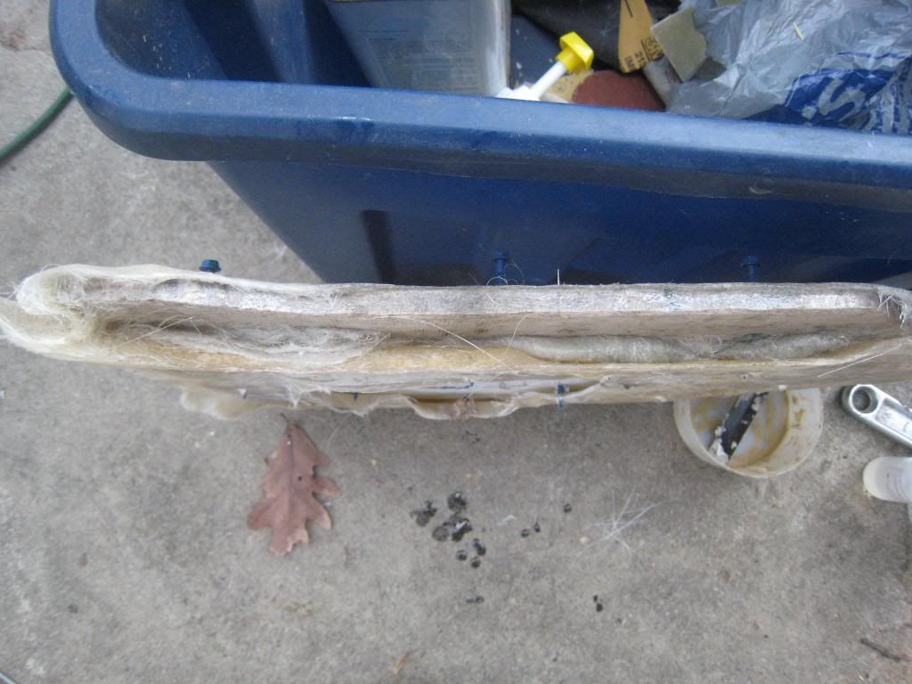
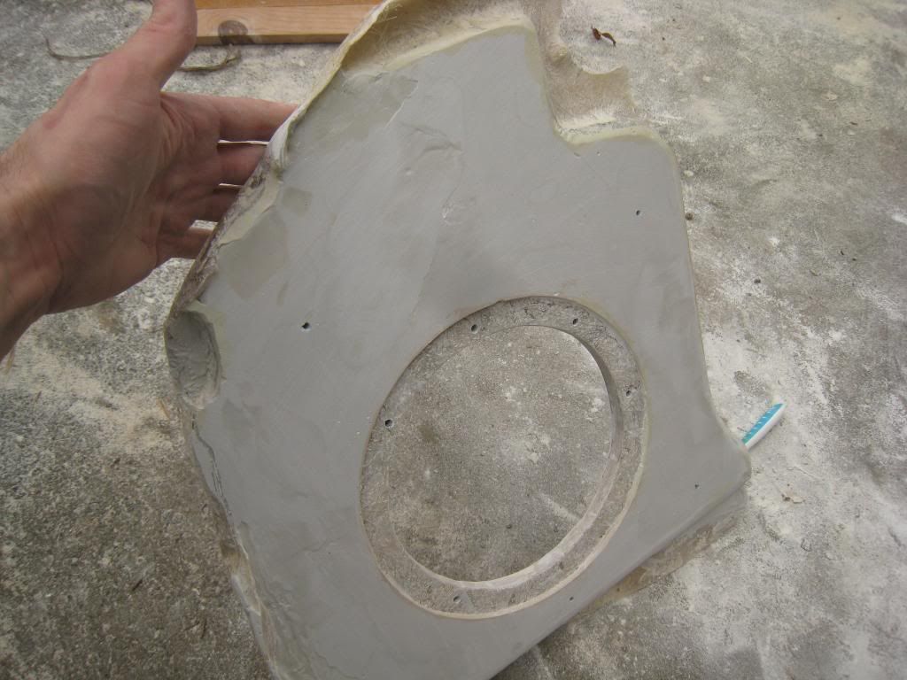
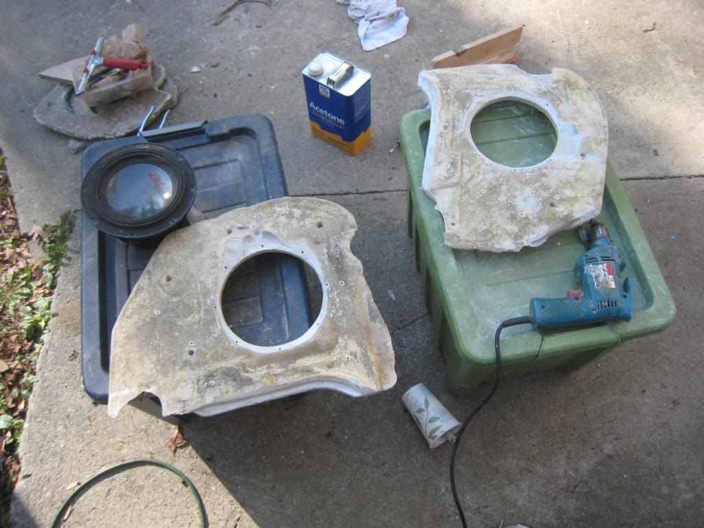
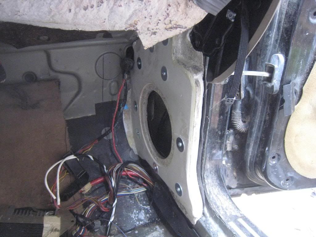
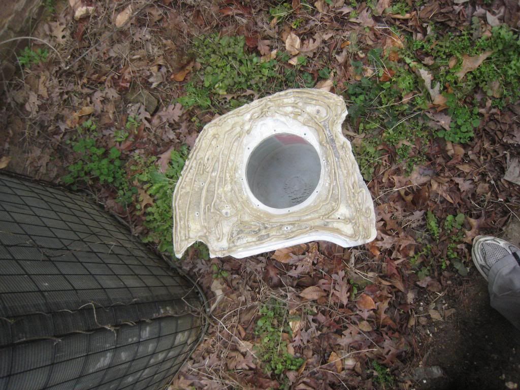
After trying many different things in this car, I finally decided to use its configuration to its fullest advantage. E34 are blessed with large, deep and voluminous kick panels with 3" thick carpet and padding underneath. Its a lot of space!

Goals:
1) Keep it relatively inexpensive.
2) Optimize for two seat listening (sinful, I know).
3)Make it sound great, in both tonality and image.
4)Use minimal equipment and minimal external processing while relying heavily on physical positioning.
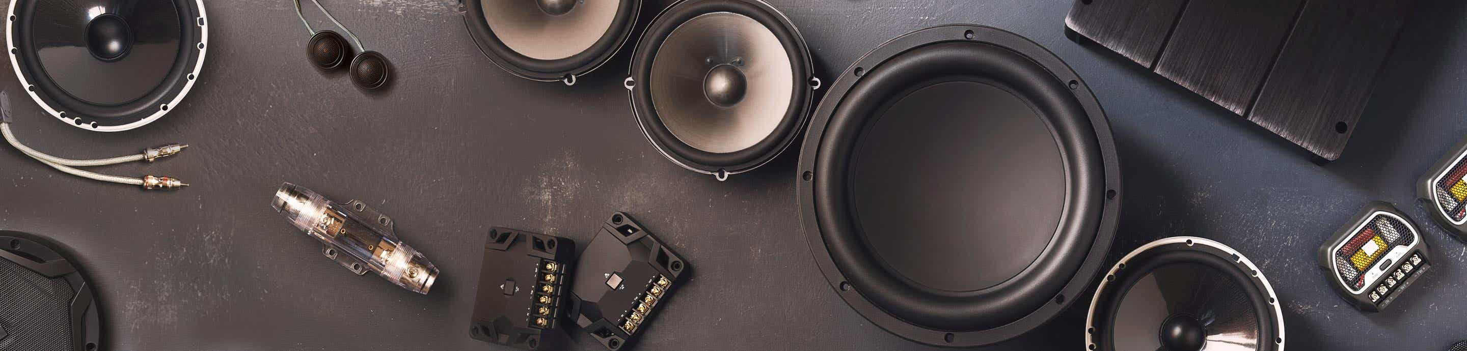
Equipment:
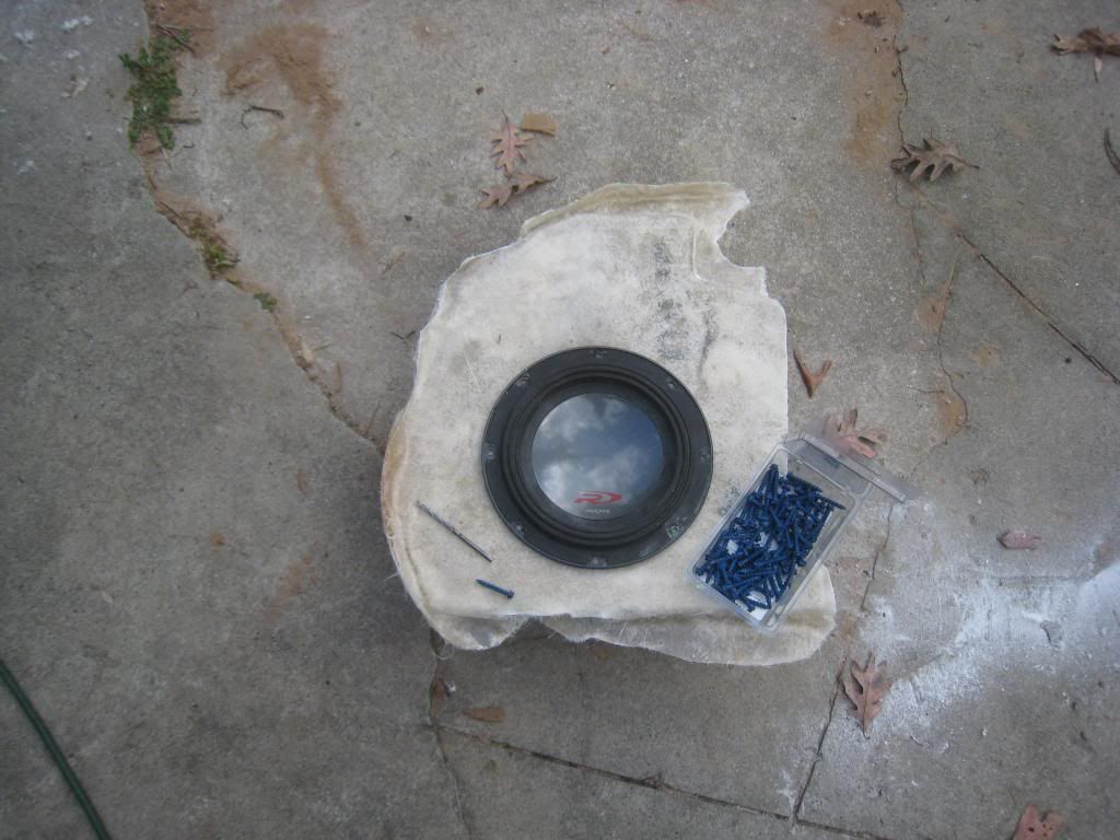
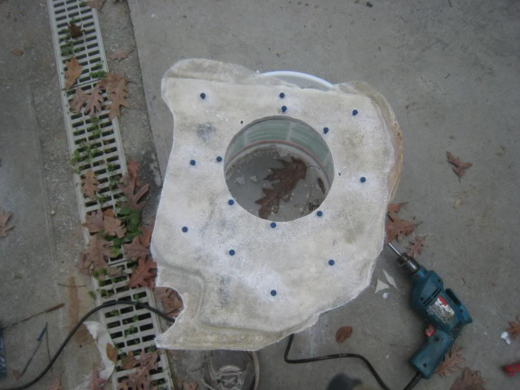
1)Two SWR-823D as sub/lower midbass hpf~125-170hz.
2) Two Celestion 5" Neodymium mids for upper midbass/midrange.
3) Two Cdt HD-100 tweets and EX-550i passive crossovers.
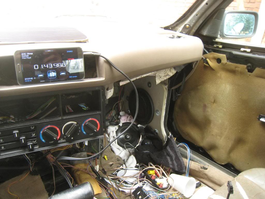
4) Samsung Note II as head unit.
5) 5 channel Kicker Amp

The type Rs were a no brainer for sub and lower midbass, inexpensive and sound fantastic

The Celestions I picked up for $9 a piece from PE during a sale on top of buyout. They were designed for acoustic guitar amps, but response curves look good.

The Cdt tweeters and crossovers were scavenged from a previous build. Crossover from mid to tweet is 2500hz at 24db slope.

The Kicker amp is nothing special, 4 channel plus Class D sub channel. 2 channels will power the Celestions, crossover, and tweeter. The type Rs will run mono off the Class D section. 2 channels will remain idle for now. I will use the built in crossovers.

I got rid of cable and internet to save money. I was due for an upgrade with my mobile. So I needed a new phone, with a large screen and large data plan. So for an upgrade of my nearly 3 year old MyTouch Slide, I went for the Note II. The really, really nice thing about the Note II is a well implemented, built in Wolfson DAC. It sounds very nice :). The stock media player has a 7-band eq, various effects options, and can play both wave and flac files and many others. 8gig built in memory, 64gig expansion, unlimited 4GLTE, cloud storage, ect. Truly a great all in one device which just so happens to have excellent sq capability.
 
#2 ·
The build gets a bit unconventional with materials, but there is good reason for it. The basic configuration is the 8" Type Rs flush mounted into the stock kickpanel openings. They are sealed. I estimate about .3 cu ft of volume once various electronic boxes were relocated. The actual volume may be way larger, as the sill area is very large and open and runs down the length of the car, but its not easy to estimate.

The tweets and mids are mounted essentially on the same baffle in .2 cu foot enclosures directly below the Rs. Remember the 3" of padding I mentioned above? Well that has allowed me to build very nice sized enclosures that will allow for many different drivers and cossover points down the road. The baffles are angled so that the tweeter sits slightly further away and off center to the mid but at the same physical distance to the ear. In testing I found that this allowed for very good mid to tweeter transition. I honestly cant hear them as separates.

Pics, some video to come.:D
 
#5 ·
I didn't either, I dont think it has really. I just stumbled on the stuff at the local big box building supply. I was simply looking for something strong, stiff, uniform, dense and thin. It fit the bill...mostly. Specifically, I used Hardie Backer. Not all backers are created equally. Retrospectively, I have discovered that it has been used to line speaker enclosures in home audio applications. There are drawbacks, especially when trying to tool the material. Straight lines, like in a shower stall, no problem, just score and break. Anything else get difficult. More on that later. ;)
 
#9 ·
Shocking revelation in the area of car audio...some things have changed. I fully intended to complete the system outlined in the initial post. But after hours of testing, and positioning, and more testing, I found that I was running into problems. To top it all off, the weather here is been a bit absurd. I don't remember the last day that it didn't rain.

The 8" type Rs are great. However, they are really designed with the idea of small box and tons of power. As far as midbass, they do a good job to a point, but they are not as flexible in frequency response as a true midbass speaker. The kick panels in the E34 have lots of volume, more than what the Type Rs really need for sealed box . So, why not use the extra volume and work Hoffman's Iron Law to my favor? Out go the 8" Type Rs. I slightly enlarged the hole in the cement board baffles to fit 8" Dayton RS225-4s. With the RS225-4s I get 6db more sensitivity, much more cone area, and much more system flexibility. I lose xmax and power handling, but I didn't have much power to play with anyway.

With system simplicity in mind, I decided to ditch the two-way passive system and give some fullrange drivers a try. There are many drivers that intrigued me. Inevitably, when one researches fullrange drivers enough, one runs across their use in line arrays. This caught my interest as a major aspects of line arrays is the ability to direct sound. This aspect of arrays has its advantages and disadvantages; but in car audio where near reflections are a constant menace, I figured I could use it to my advantage. I scrounged up my 15 year old drivers from a Cambridge Soundworks 5.1 system I used on my first PC build Hardware One - Review Printout. The FL, FR, RL, and RR drivers are self contained and identical. I hot glued two of them together to create a two driver array for each channel as proof of concept. I placed the makeshift arrays vertically below the RS225-4s. I listened for a couple hours and I was fairly impressed with the results.

So I set about the process of looking for drivers that I could utilize in a similar fashion to the test array. I needed something between 2-3" with an fs of at least 150hz and the ability to play high enough to dismiss the tweeters. I looked at numerous drivers from TB, Dayton, Peerless, Fountek, Fostex, and even Mark Audio. In the end I settled on a driver designed specifically for arrays. Compact Array - AN2775 - Celestion - Guitar, Bass & Pro Audio Speakers
Not exactly inexpensive, and very new to the market and as result they are a bit of an unknown. But they seemed to fit my needs.

So now I am going subless and tweeterless two-way kicks :p. Still using the kicker amp and the Note II. I have a four day weekend and no excuses. Initial testing has been interesting.

BTW, its absolutely pouring down rain again :worried:. Hopefully there will be some breaks this weekend so i can get to work.
 
#11 ·
Need moar pics. :p I like where this is going
 
#13 · (Edited)
So I have made a bit progress, but I wanted to go back and start with the build of the baffles for the kickpanels.

Image


The above picture is where things started with the Type Rs. The original baffles are made from MDF. But after making the baffles, there were some things that I didn't like. My initial grievance is that I hate the stuff. I really hate working with MDF, I don't like it's vulnerability to moisture, and I don't trust the quality.

Image


On the practical side, there were other concerns. The MDF pictured is 3/4" thick. The kickpanel area that they were to be mated to appears mostly flat, but it is not; there are lots of creases and folds in the metal to add stiffness. To get the MDF panels to mate in a form fitting fashion to the kickpanel sheet metal would have resulted in a baffle that is almost 2" thick. While a 2" thick baffle may not seem to be an issue by itself, there were less then desirable obstacles. I was not willing to cut much sheet metal. With a 2" thick baffle, air could not escape from the back side of the driver cone without a good amount of chamfer. That chamfer would have necessitated the enlargement of the kick panel opening in the sheet metal by several inches all the way around. The other issue was that any additional intrusion into the footwell area would compromise the width and positioning of the other drivers.
 
#14 · (Edited)
Time for a plan B. I went on the hunt for a material the was thin, stiff, fairly strong, very dense, and most importantly, very inexpensive. I was at the local big box store, and happened across cement board. Cement board is used as a backer for tile in shower stalls and such. There are different kinds, some quite fragile. The stuff I got was reinforced with a fiber matrix, hit all the criteria mentioned above, and was only $10 a sheet. For that price, it was worth it to try something unconventional.

Image


I started by taping up the kick panels to make fiberglass molds that fit exactly to the sheet metal. Fiberglass mat and polyester resin was used to reduce cost. Carnauba car wax plus hairspray was used as release agents over the tape. I wont bore you with picture of the glassing, but suffice to say its a ***** to lay on your side, in the foot well, while stippling glass at arms length.

Image


Jumping ahead a few steps. You can see the fiberglass piece molded perfectly to the kickpanel sheet metal. The piece that is on top of that is the cement board. I used the previously cut MDF baffles as templates for the cement board. Cutting the cement board was a serious *****. The typical method for cutting the board is to score and break. That method is great if you are making long, straight cuts (like for a shower stall). But I needed to cut circles and compound curves. I turned to my trusty Makita jigsaw. I had a few dull blades and some new ones. The initial cuts proceed quickly, but the cement board eats the blades within minutes. The blades would abrade and narrow quickly in the center (in the section of the blade that passes through the cement board the most times), and the narrowing blade would eventually start to grab and vibrate the cement board as the blade reciprocated, due to the difference in thickness of the blade. To get the blade to last longer, I would actually vary the cutting depth of the blade while making the cut by lifting the jigsaw off the surface. This allowed the blade to wear more evenly and I was able to mitigate the grabbing of the cement board caused by uneven wear. However, the teeth would still round over completely and eventually I would have to change blades. In all, I think I wasted about 10 blades. The blades are not that expensive, less then $10 for a pack, so it was not much of a loss. There are carbide encrusted blades that would have done the job, but I didn't have access to them, and they most likely would have been more expensive than an entire pack of regular blades.

If you look around the edge of the cement board piece, the gray coloring is actually metal from the blades which is has abraded and embedded into the cement board :D.
 
#15 ·
Looking good. How will you attach the cement board to fiberglass? Resin? Nice unique approach.
 
#17 · (Edited)
Image


Another look at the cement board and molded fiberglass piece.

Image


With the cement board and molded fiberglass piece out of the car, you can see the various contours of the sheet metal. The space between the cement board and molded fiberglass piece will need to be filled. The outer skins of fiberglass plus the inherent strength of the cement board provide more than enough strength and stiffness. The material used to fill the voids only needs to have have some compressive strength. The sharpie line is an area of the fiberglass that will be trimmed.

Image


A view from the outer edge. The cement board is 3/8" thick, half the thickness of the MDF of the original baffles. At 3/8" the cement board is just as stiff and more than twice as dense as the MDF.
 
#19 · (Edited)
Image


I started the process of filling the void between the cement board and molded fiberglass by sealing one edge at a time with tape. Then I mixed a polyester resin / body filler slurry which I could pour down, from the speaker cutout, into the taped off area. I did this about four times for each baffle. The cement board is slightly porous. It will soak up some resin and allow for good bond strength between it and the molded fiber glass piece. The end result was that the cement board and fiberglass piece adhered to each other and baffle was sealed around most edges. Then I did some lay-up of fiberglass mat over the exposed face of the cement board.

Image


Again, I won't bore anybody with the fiberglass steps but the end result is pictured above. The molded fiberglass piece has been trimmed along the sharpie line to accept the driver basket.

Image


The assembled baffle back in the car for a test fit. The exposed face of the cement board has been fully glassed over. There is a gap around the edge where the baffles meets the firewall. Originally I had thought that some shrinkage had occurred, which is a potential problem with polyester resins. But after some repositioning, the baffle fit exactly to the sheet metal. Notice that I glassed some flange area between the kickpanel and the firewall.

This picture also gives some sense as to how much volume is available in the E34 kick panels. The space is essentially hollow from the kickpanel up the A-pillar and down the sill plate of the unibody. Lots of volume to work with.
 
#20 ·
Since it will never stop raining, I guess I have to shelve the work I had planned for today. But, I guess that gives me the opportunity to post some more of the build.

Image


This is a quick test fit I did of the Type Rs. The blue screws are special cement screws. The drill bit has a carbide tip and came with a kit that included the screws. I think it was about $10. I wanted to try to use the screws to secure the drivers and also to attach the baffles to the kick panel sheet metal.

Image


Image


There was also another purpose behind the screws. Since I needed to fill the voids between the molded fiber glass section and the cement board, I was somewhat concerned with the possibility of the fiber glass piece bending or warping during this step. I planned to stuff the larger voids with resin soaked glass and then pour polyester resin / body filler mix into the smaller voids. To avoid flexing, and thus ruining the overall shape of fiberglass section, I used the cement screws at strategic locations to prevent flex in the fiberglass section while filling the voids.
 
#21 · (Edited)
Image


Pictures of the stuffing process just to get an idea of how it was done. Nothing too complicated here. The glass was over saturated with resin, and I spent a good amount of time stuffing the glass into the space to prevent voids. Before the glass cured, I quickly made a fairly low viscosity polyester resin / body filler mix to pour over the stuffed fiberglass. I then used my palm sander to vibrate the baffle to work out trapped air and voids.

This was somewhat tricky work in regards to the amount of catalyst used. Too much catalyst, and the mix would kick off before I would be able to work out the bubbles. Too little and it would never cure. The fact that the area was mostly enclosed, was an advantage. It allowed me to use less catalyst, and once the cure started to kick, the heat generated in the enclosed area would help to ensure complete cure. Small bubbles left behind are not a great concern, but ideally I wanted to eliminate the bulk of them.

Image


A picture of the void filling process. I had just finished filling the open edge of the baffle on the right. With the baffle on the left, I had started to fill the voids from the opening of the speaker cut out. Again, the blue cement screws are used to maintain the shape of the fiberglass section during the void filling process.
 
#22 ·
Image


After doing multiple rounds of void filling, the molded fiberglass section and the cement board were finally a solid, single baffle. The next step was some cosmetic filling. The surface does not need to be perfect here because the baffles will be covered with 1/2 acoustic foam and grill cloth, but it does need to be level. I dammed up the edge with body filler and used the circular gasket from the type Rs to create a counter sunk area for the subs.

Image


Here is the cosmetic filling I did on the first baffle. Again I used a polyester resin / body filler mix. This mix was thicker than the mix I used for void filling. In fact, the mix here was too thick. The idea is that it would be self-leveling, but you can see it did not level properly. Yep, thats crappy body filler in the background :). I wouldn't use it for much else, but talc is talc and I am just using it to fill voids.

Image


Both baffles after cosmetic filling.

Image


More sanding than I cared for. Live and learn. But you can see the baffles are finally starting to take shape.

Image


Quick test fit. There are still some imperfections on the face that will need attention. At this point the baffles are quite heavy for their thickness. They are very solid and strong too.
 
#24 · (Edited)
I would hesitate to make a definitive statement in regards to resonant frequency without actually measuring it. But they seem to be less resonant than 3/4" MDF. I think I actually have video of me striking the surface to show how dead they are; It was like punching concrete. There is another where I pound on the baffles when they are mounted to the sheet metal of the kick panel, and the only thing you can hear is the door rattling. I will try to post those videos at some point.

One thing is for sure, they are extremely stiff. Far stiffer than MDF alone, and stiffer still than MDF / fiberglass composite panels I have made in the past.

They are mostly bomb proof, with some caveat that resulted in a design change when I switched the Type Rs for the RS225-4s. I will give details of that later on in the build log.
 
#28 · (Edited)
Image


Quick look at the passenger side baffle out of the car. Obviously there is still some cosmetic work needed.

Image


A look at the back side of the baffles. I think this is the first picture I have posted that you can clearly see the different ridges and contours of fiberglass section which was molded to the sheet metal of the kick panels. There is a good amount of mass to those baffles. You can also see my trusty Makita drill; its a good 20 years old :).
 
#29 ·
Image


Another test fit. This time the baffles have been bolted to the sheet metal. I was somewhat concerned with spreading the load over the surface of the baffles. I was finding that I needed to torque the sheet metal screws to a greater degree than I had originally envisioned. The original plan was to counter sink the screws into the cosmetic surface so that the face of the baffle would be flat, and I would be able to apply whatever finishing surface I wanted (grill cloth, micro suede, vinyl, ect) over that. But with the need for the washers to spread the load, the original plan would not work.

Image


Just messing around and having fun with different arrangements and drivers here. You can see the Note II with Wolfson DAC. The media player is Neutron player, which has some good features such as 4-band PEQ, ability to adjust channel cross-talk, echo, reverb, and other effects and DSP like abilities. No TA though. Its hard to tell in this picture, but I have also cut the carpet back to make room for the midrange enclosures.
 
#30 ·
Image


I apologize for the rather low res quality and glare in this picture. I think this was a picture taken with the Note II. The main reason I am showing this picture is because of an additional feature I did not mention before. If you look carefully, you can see some thin, black material sandwiched between the baffle and the kickpanel sheet metal. That black material is actually 1/8" thick neoprene. The thought was to make a gasket layer between the baffles I made and the sheet metal. The idea was that this would seal imperfection, allow me to remove the baffles if needed, and hopefully provide a dampening layer between the drivers and baffle and the body of the car.

Well that idea did not work so well. It did fine for casual listening. But as I turned up the volume, I could detect some resonance of the sheet metal to which the baffle was bolted. I spent some time retorquing the screws. I would let it sit for a day, then go out and retorque them again. These steps did help some, but they did not solve the issue completely. But I had planned for the possibility of failure here.

Image


The solution came in the form of a tube :D. This a less than ideal solution, because I would have preferred to have the ability to remove the baffles if needed. This solution is nearly permanent. But, this where the extra flange area that I built into the baffles (which I mentioned earlier in the thread) will be of great benefit. Mostly useless in the case of fastener attachment, the flange areas change the direction of force to compression and elongation, and adds surface area for the adhesive. It always I good idea to plan ahead, just in case your first option fails to meet expectations ;).

Image


Gut check! No turning back now!