
Hey guys!
I know the 505 is an older model, but hopefully this may help those who are still rocking this deck and (like me) will not pay the $100 or so for the proprietary Alpine digital cable (KWE-610A).
So here's a step by step for doing your very own Toslink conversion, of which I have tried to take as much guess work out as possible.
Here's what you'll need:
1) PLT133/T Fiber optic transmitter (Digikey part no. 108-1428-ND) Digi-Key - 1080-1428-ND (Manufacturer - PLT133/T)
2) 0.1 uf capacitor (I had one laying around) Radio Shack part no. 272-0135
3) Soldering iron & solder
4) Small flexible cable (18-22ga should be fine)
5) Small heat shrink tubing
6) Patience")
Ok so here we go:
Remember, you can always click the image for better detail in full scale!
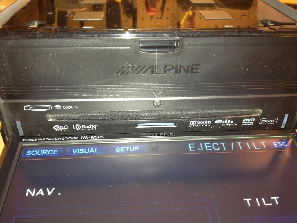
First, open the face and remove the small black screw in the center of the back panel
![Image]()
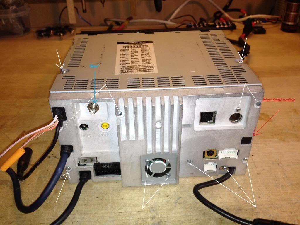
Next, remove all of the indicated screws as well as the 8mm nut for the gps antenna jack.
![Image]()
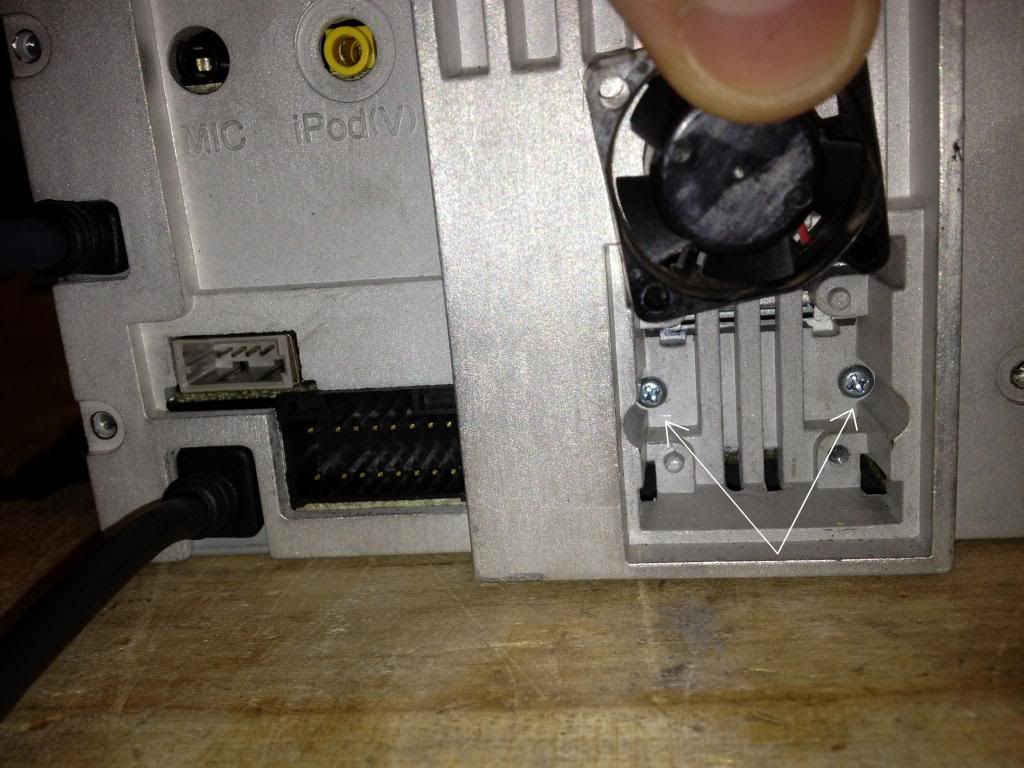
Flip up the fan and remove two screws
![Image]()
Remove the top plate, disconnect the fan plug and then remove the back plate
![Image]()
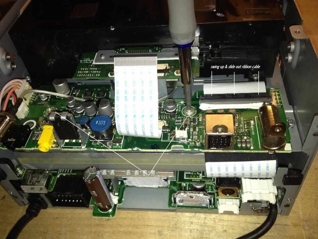
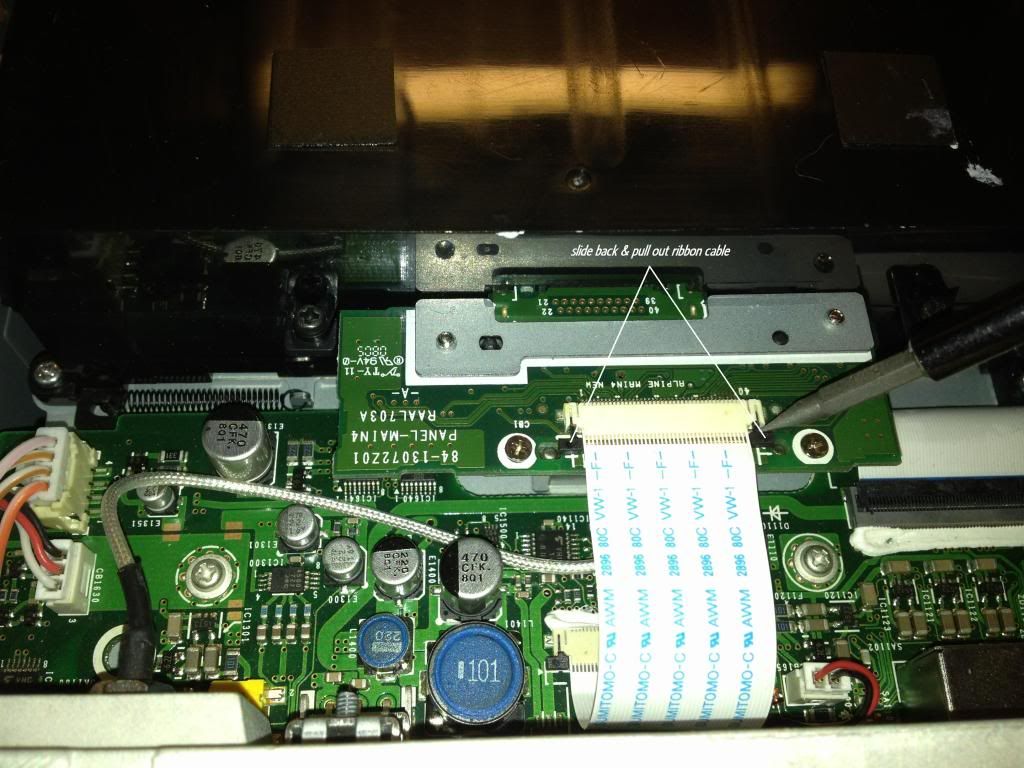
Remove the two large ribbon cables, two mounting screws and remove this board
![Image]()
![Image]()
Remove four screws that secure the GPS housing and remove it.
![Image]()
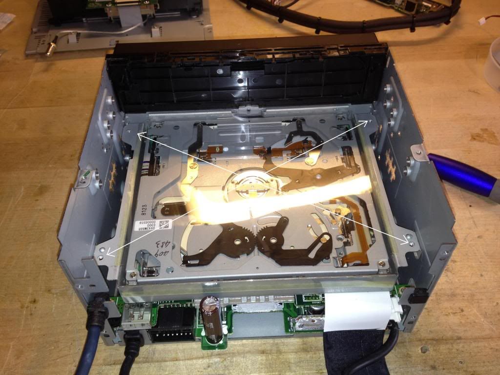
Remove four screws for the DVD transport
![Image]()
I know the 505 is an older model, but hopefully this may help those who are still rocking this deck and (like me) will not pay the $100 or so for the proprietary Alpine digital cable (KWE-610A).
So here's a step by step for doing your very own Toslink conversion, of which I have tried to take as much guess work out as possible.
Here's what you'll need:
1) PLT133/T Fiber optic transmitter (Digikey part no. 108-1428-ND) Digi-Key - 1080-1428-ND (Manufacturer - PLT133/T)
2) 0.1 uf capacitor (I had one laying around) Radio Shack part no. 272-0135
3) Soldering iron & solder
4) Small flexible cable (18-22ga should be fine)
5) Small heat shrink tubing
6) Patience
Ok so here we go:
Remember, you can always click the image for better detail in full scale!
First, open the face and remove the small black screw in the center of the back panel
Next, remove all of the indicated screws as well as the 8mm nut for the gps antenna jack.
Flip up the fan and remove two screws
Remove the top plate, disconnect the fan plug and then remove the back plate
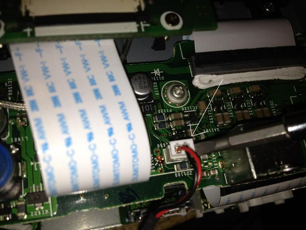
Remove the two large ribbon cables, two mounting screws and remove this board
Remove four screws that secure the GPS housing and remove it.
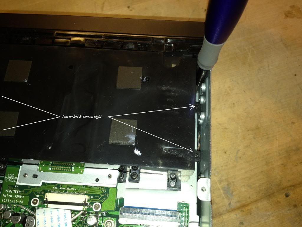
Remove four screws for the DVD transport