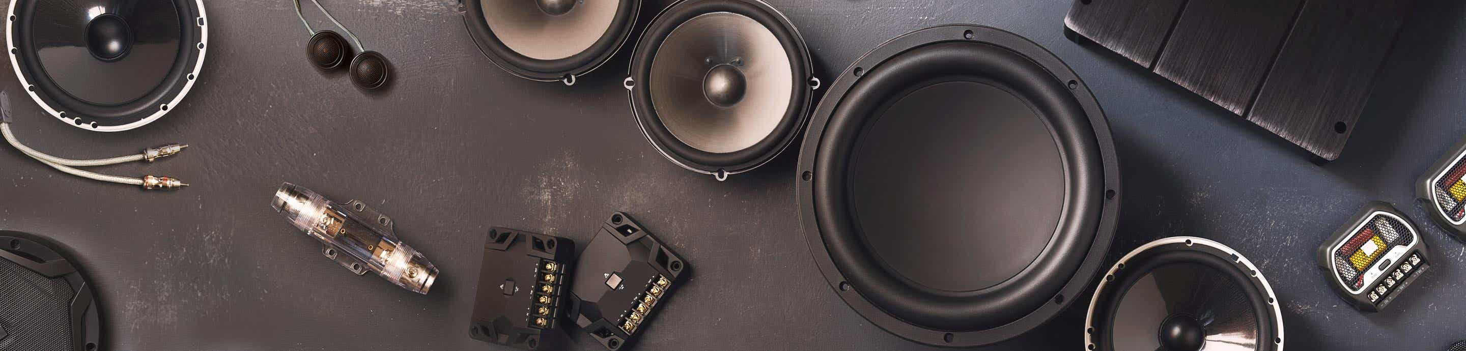

Designing a turn on/off delay circuit is quite simple and will cost you no more than $5 to make. All parts can be picked up from Radio Shack or Fry's if you have them as well as Parts Express. This will cover the mechanical aspects of it - theoretical topics can come later. If you suffer from pops on your amps or any other components, this will help you eliminate it, but it does not work in all cases.
You will need the following parts..
1 12 volt SPDT 30 amp relay
1 NPN Transistor
1 Diode (same one installer uses in alarms)
1 capacitor with either different values of 100uf to 1000uf, polarized electrolytic, 16 volts or higher
1 few small fuse holders (for safety issues)
Start off with your turn on lead or ignition switch from your head unit. Wire in series a diode with the stripe facing towards the amp. (you can put a 1 amp fuse here in case you short out the turn on lead.)
Next, wire the capacitor after the diode and ground it. The higher the impedance on the capacitor, the longer it'll delay.
After the capacitor, the transistor is straight forward, wire the turn on lead to B, 12 volts to C, then E out to the relay.
For the relay, use 86 as the input from your turn lead lead, and ground 85. Wire 12 volts to 87 (make sure you fuse this) and 30 out to your components. When the coils are energized, 87 and 30 will be connected and will send current to your devices.
I forgot where I found this saved imaged file from, but it's the best one I could find...
![Image]()
You will need the following parts..
1 12 volt SPDT 30 amp relay
1 NPN Transistor
1 Diode (same one installer uses in alarms)
1 capacitor with either different values of 100uf to 1000uf, polarized electrolytic, 16 volts or higher
1 few small fuse holders (for safety issues)
Start off with your turn on lead or ignition switch from your head unit. Wire in series a diode with the stripe facing towards the amp. (you can put a 1 amp fuse here in case you short out the turn on lead.)
Next, wire the capacitor after the diode and ground it. The higher the impedance on the capacitor, the longer it'll delay.
After the capacitor, the transistor is straight forward, wire the turn on lead to B, 12 volts to C, then E out to the relay.
For the relay, use 86 as the input from your turn lead lead, and ground 85. Wire 12 volts to 87 (make sure you fuse this) and 30 out to your components. When the coils are energized, 87 and 30 will be connected and will send current to your devices.
I forgot where I found this saved imaged file from, but it's the best one I could find...


