DIYMobileAudio.com Car Stereo Forum banner

6.5" tangband 30 hz Tapped Horn

15K views 28 replies 10 participants last post by  bkjay  
#1 · (Edited)
So I am in the process of making this neat little tapped horn for the 6.5" tang band i had laying around from a previous project. I wanted to use it for something so i went searching the internet and came upon this website:

Tapped Horns

Looked around a bit and found he had some plans for this exact driver. So i downloaded it and have finally gotten around to making it. The plans are Here:

http://www.volvotreter.de/downloads/TangBand_W6-1139SC_Horn_Rev_1.pdf

I converted all the metric into our standard system which was a pain. I used 1/2" particle board for the inside pieces and couldn't find any 5/8" for the outer parts so i changed some measurements to accommodate 3/4" since i had some laying around.

After making the converted cut list I made all the cuts and labeled them with letters. I don't have any pics to put up right now but i will later tonight. I have all the internals put together i just need to add the sides then do some finishing touches on it. (like use my new spray gun to paint it :D)

I will eventually get the Dayton 100 w Plate amp for it but i will use my 240 w amp i have to test it out. This will eventually (once finished) be placed behind the couch at my g/f's house for her Dad since he is using my other one i built here:

http://www.diymobileaudio.com/forum/diyma-build-logs/61999-idq12-dual-p-r-s-home-theater-sub.html

So he will receive the smaller one yes, but hopefully it will still please him so i can have mine back ;)

I plan to have this finished by the weekend with a bit of a review (non-technical)

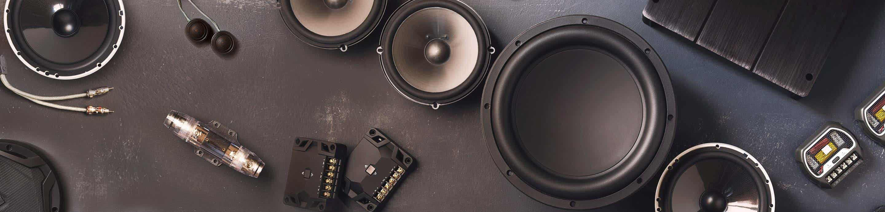
A bit of a teaser Pic:
 

Attachments

#3 ·
Guess i will find out. I am doing it on a small budget so it will work for what i need it to do.
 
#4 ·
So I ended up cutting all the wood and labeled it with letters like I said in my previous post. I then put foam stripping around the face of the sub and mounted it into the baffle.

Image


Image


Image


Image


Image


Image


Now this was the tricky part. I had some braces added to make it more solid and the way I would have to do this to be able to screw them together is a bit complicated and annoying. I had to put two sides on. Then screw through both sides ( not using glue at first so I can take it apart in the next step). Then take the side on the right off and put the next one to the left of the one still left.

I know this is confusing but just look at the pictures. You will understand it better.

Pictures in next post:
 
#5 ·
This is with the third board in place already. But Just imagine that is not there. So I added the two braces I had and screwed through both sides:

Image


Image


Then I missed another picture but I added the brace between piece 2 and 3 then took #2 off and added #4 and its braces:

Image

Image


Then took #3 off and added #5 and its braces:

Image


And now is the part where I worked backwards. I had to take #5 off because I need to get at the screws for the smaller board at the bottom. I glued and screwed these all in place.

Image


And finally came to this: (well almost)

Image
 
#6 ·
Now with this design, the mouth of the horn goes past where the sub is, so there is an access panel that is designed into it. So it makes it easier to take the sub out or replace it. I bought some aluminum plating that is 1/16” thick by 1.5” or something close to that width. This will be for the bottom of the access panel. Then I bought ¾” 90 degree aluminum bracketing. This will go onto the wall of the mouth area. Pictures will explain it better as I get to those points.

Image


Image


And this is where I am at now:

Image
 
#8 ·
Nice. I've been looking into box designs lately and always wonder what program or method people use to make tapped horns, transmission lines, etc. I have bassbox pro and for some crazy reason it won't let me do a slot port. Anyways, looks good. That particle board isn't what I'd personally use but since it's low power AND ported I don't see it being that big of a deal. Nice work. Sub'd.
 
#9 ·
I will eventually get the Dayton 100 w Plate amp for it but i will use my 240 w amp i have to test it out. This will eventually (once finished) be placed behind the couch at my g/f's house for her Dad since he is using my other one i built here:

So he will receive the smaller one yes, but hopefully it will still please him so i can have mine back ;)
I think he will be happy to have this, once you are done !:)
 
#10 ·
I'm looking forward to hearing it since i have never heard a tapped horn before. If it turns out really nice i might make one for me since my other one is so big.
 
#11 ·
Update:

I got most of it together. I got the three rails cut and attached:

Image


Image


Image


Then I got all the sides put on and this is where I am at now.

Image


Image


Image


I Just need to go get 8 bolts with some locking nuts to hold the access panel on and attach the top panel. Hopefully I will be able to test it out later on today.
 
#12 ·
Ok So i got it all together, at least roughly to test it out. And all i can say is WOW. This thing is incredible. It shakes the walls and everything. It does roll off the lows right after thirty though (tuning point i know) but it still kicks ass. I have some more pics i will post tomorrow and maybe a video or two of it shaking stuff. If you have some free time make this! you won't be sorry.
 
#14 ·
#15 ·
That looks awesome! What did the total volume(gross)end up being?
 
#16 ·
I honestly don't know. I just copied the plans from that link in the first post. I can measure it if you really want.
 
#19 ·
Stay with the 240W amp and call it the day, $30 savings might not be worth it afterall.
 
#20 ·
Sounds good. I will just have to tell him that he needs a $140 amp instead of 110. Oh well. I am letting him use my 240 watt one until he gets his amp.
 
#21 ·
Ok so some more pictures of where it is right now.

I put foam stripping where all the walls met up so i could make sure it sounded good and i had access to all the screws for the access panel without having to make the top removable. It also helped me figure out that the sub was a bit leaky around the flange which was causing some chuffing:

Image


Foam stripping on the access panel flanges:

Image


I rounded over the inside edge of the access panel to reduce chuffing which was a major issue. I now feel like i should have rounded over the other edges on the inside. But it sound okay now so i think it is good to go without doing that.

Image


I also rounded over the inside edge of the mouth to stop a lot more of the chuffing:

Image


So now it is sitting behind the couch in the test phase to see how he likes it. I will probably wait till this weekend to start doing the finishing process which will include filling all the screw holes, some bondo work around the edges, then sanding and then painting. I will see what he wants to do but it will most likely be black.

I will probably find a way to attach the amp to the box by adding onto one of the ends. Since the amp is a little bit longer then the height of the box i will need to make it go on sideways. It will have a pocket to go in that is recessed enough so the fins do not go past the edge of the box. I will try to draw it out to explain it better.
 
#23 ·
I don't these plans were for the 6.5 tangband. It will vary depending on the sub being used. Do some research and try to find hornresp to design a horn for another sub.
 
#25 ·
Yeah its definitely worth it. I would make two of them because just one fills in the low end nicely but two would be the ideal situation.
 
#26 ·
Here are a few pictures of it behind the couch.

Image


Image


I will get it tonight to start the finish work on it tomorrow. I have also moved it from behind the couch to behind his stereo cabinet since it is right in a corner. It has really helped bring out some authority in it by being in the corner. More pictures of that will be up later on.
 
#27 ·
Ok so i got it all bondo'd up and sanded:

Image


Image


Then primered up and sanded down a bit before final coat:

Image


Image


Image


Then painted a few sides the flat black with a spray gun:

Image


Its turning out really nice but i realized i need to try and hang it if i want it to be flawless all around. So i come up with this little err big jig to hang it up.

Image


Getting help from the access panel guides, i screwed an L shaped piece of wood i made so i could hook a tie strap onto it.

Image


This allowed me to paint the entire thing without rotating it and messing up the finish.

Now i am putting the sub back in and the access panel back onto it.

Image


Image


Continued.
 
#28 ·
Looks very good. The spray gun did a nice job and made a smooth surface. Although i did notice one big thing.. I completely missed a corner. LOL It was the very bottom corner that was closest to the ground, i can't believe i did this:

Image


I am just going to brush over it since i don't want to get my gun all painty for that one small corner. I wouldn't bother with it normally but that is the side that will be up and visible so it needs to be painted. I will post a picture of the positioning of it tomorrow or when i get it installed at the house.