the 500E / Alpine system
Here is what I have learned so far, for the 500E which appears to be the "Alpine" version of the 2013 Fiat 500 audio system options.
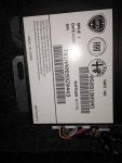
The amp appears to be a moderately powered, possibly eight channel, probably heavily EQ-ed affair, with "proprietary" connections.
The good news is that this means there is wiring from the HU to the trunk, and from the trunk to the speakers already in place. For someone like me, looking at a three figure upgrade rather than a four figure upgrade, having wiring in place saves lots of time and money. No it's not the ultimate quality and I should run new power, of course.
Now, I call these connectors "proprietary" but nothing really is in these cars. However, I am too ignorant of the terms used to sort content on mouser.com -- so I cannot find an aftermarket source for the mates to these connectors. Why do I care? Because I'd like to wire up a plug and play harness in the trunk, and not splice anything, so later on it would be easier to either swap back in the OEM amp (like for a lease return) or to upgrade to a different amp, without doing more splices.
SO, if someone recognizes these connectors, please speak up
")
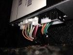
*Wiring in trunk:
**Big Connector with #1-12 on top row and 13-22 on bottom row:
1, Ground
2, blank
3, Red/yellow = remote turn on
4, Orange/brown = LR+
5, Green/red = RR+
6, Yellow/gray = LF+
7, Purple = RF+
8, Brown/yellow RF+ tweeter output
9, White/green = LF+ tweeter output
10, blank
11, blank
12, +12VDC Power
13, blank
14, blank
15, Orange/blue = LR-
16, Green/white = RR-
17, Yellow/green = LF-
18, Purple/white = RF-
19, Brown/red = RF- tweeter output
20, White/blue = LF- tweeter output
21, blank
22, blank
**Little connector, pin # 1-8 top row, 9-16 bottom row. Amplifier speaker outputs [except tweeters]
1, blank
2, blank
3, Gray/white = Subwoofer for Beats option [n/c on non-Beats]
4, Green = Right Rear
5, Orange/black = Left Rear
6, Green/gray = Subwoofer for Beats
7, Purple/orange = Right Front mid-bass
8, Yellow = Left Front mid-bass
9, blank
10, blank
11, Green/white = Subwoofer for Beats
12, Green/black = Right Rear
13, Orange = Left Rear
14, Gray/brown = Subwoofer for Beats
15, Purple/black = Right Front mid-bass
16, Yellow/red = Left Front mid-bass
-------------------------
And though I don't have a photo of it, the HU output is apparently:
*Head-Unit connector, speaker-level outputs to amp in trunk:
Orange/brown = left rear positive
Orange/blue = left rear negative
Yellow/gray = left front positive
Yellow/green = left front negative
Purple = right front positive
Purple/white = right front negative
Green/red = right rear positive
Green/white = right rear negative
-------------------------
Big thanks to the guys on the Fiat forum for help with identifying what the wiring is all about.